
partnerünk K+F eredményei és tapasztalatai
Partnerünk a HIDRA Felnőttképző Központ Kft. K+F pályázat kapcsán a műanyagok és kompozit anyagok vizsgálata terén végzett hiánypótló munkát és szerzett komoly tapasztalatokat. Örömmel teszünk eleget a felkérésüknek és osztjuk meg a munkájuk eredményének a leírását:
Bevezető
Az alapanyagokkal és gyártástechnológiákkal való megismerkedés mellett részletes kutatást végeztünk a roncsolásmentes anyagvizsgálati eszközök területén. Ennek eredményeként eszközmódosítást kértünk a pályázatban.
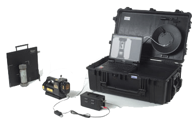
This modification was necessary because since the submission of the tender, more modern, more technically advanced and more versatile material testing equipment has appeared on the market. The previously planned phosphor plate radiography system has been replaced by the latest state-of-the-art inspection technique and procedure, a pulse radiography system with an integral digital detector.
A rendszer teljesen számítógép vezérelt és a biztonsági követelményei is jóval alacsonyabbak, mint egy hagyományos röntgenkészülék esetében, amely az expozíció során nem impulzusokat, hanem folytonos sugárzást bocsát ki. A pályázat beadása és megvalósítása között eltelt idő alatt technológiai váltás az ultrahangos vizsgálóberendezéseket illetően történt. A két fent említett eszköz mellett egy digitális mikroszkópot szereztünk be. Ezzel új lehetőség nyílik a roncsolásmentes és a roncsolásos vizsgálat területén is. Az említett eszközök a vizsgálati tevékenységen túl, annak oktatására is tökéletesen felhasználhatók, így nagyban hozzájárulnak a sikeres kutatás-fejlesztés projekt megvalósításához.
It was important for us to get a more complex, complete and comprehensive picture of each area of non-destructive testing, so we looked in detail at the different areas, procedures and methods of non-destructive testing. This knowledge is important both for research and development purposes and also because we intend to use the equipment acquired in the course of the project for further materials testing activities and, as mentioned above, for educational purposes. We have focused on radiography, ultrasonics, phased array ultrasonics, but also, due to possible changes in the tender and to gain a broad knowledge of the field, we have also explored other non-destructive material testing techniques. The starting point for the knowledge gained is, of course, the field of metals. For metals and alloys, these procedures have been used for decades, the methods are standardised and the evaluation criteria are based on detailed fracture mechanics analyses and practical experience.
For plastics and multi-material products, such a wide range of theoretical and practical knowledge, standardised methods and general standards are not available. In addition to radiographic, ultrasonic, phased array ultrasonic and microscopic materials testing, other methods were also studied. Visual inspection looks for large free deviations, the presence of which may lead to the product being released for further examination. The fluid penetration test can be used to detect surface deviations in any material, whether metal, plastic or composite. The magnetic materials test is only applicable to ferromagnetic materials, such as metal matrix composites. Its advantage over the penetration method is that it requires less equipment, less cleaning and post-cleaning. A more specialised test for typically pressure equipment and fabrications, the compaction test, was introduced. It is an excellent non-destructive material testing method, but less relevant to the aim and objectives of the present R&D project.
Napjainkban egyre nagyobb mennyiségben készülnek additív eljárásokkal műanyag termékek, és a jelenlegi tendenciák alapján elmondható, hogy a piaci részesedésük növekedése tovább folytatódik. Részletesebben az FDM (szálfektetéses) és az SLA (stereolitográfiai) eljárásokkal foglalkoztunk, mivel ez a kettő a leggyakrabban alkalmazott előállítási folyamat. Mivel a későbbi anyagvizsgálati rész során szerettünk volna ilyen eljárással gyártott termékeket vizsgálni, így megismerkedtünk a 3D modellezés sajátosságaival. A gyártási folyamatra jellemző termékeket modelleztünk, amiket a későbbiekben legyárttattunk a vizsgálati kutatáshoz.

Vizsgálatok


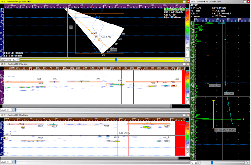
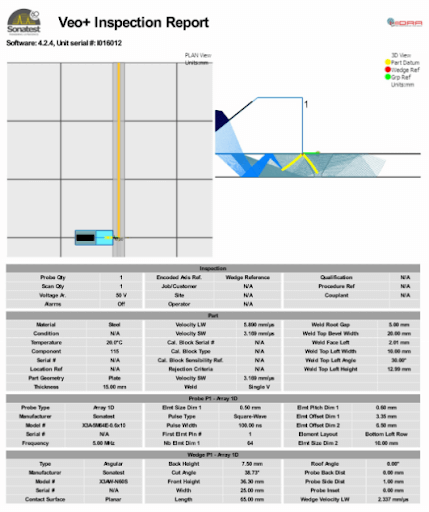
A hegesztett fémeket radiográfiai és ultrahangos eszközökkel vizsgáltuk. Mivel a fázisvezérelt technika szélesebb körben történő alkalmazása manapság még nem túl elterjedt, így a módszer megtanulása, értelmezése, és a vizsgálatok elvégzése is új kihívást jelentett. Az eszköz modernségének köszönhetően, a megvizsgált termékek eredményei az eszköz szoftvere segítségével értékelhetők. A fémek esetén alkalmazott és érvényes anyagvizsgálati szabványok biztosították a kiindulási alapot itt, és a későbbi anyagvizsgálati feladatok során is. A fázisvezérelt ultrahangos készülékből az elvégzett vizsgálat adatait ki lehet exportálni. Nem csak a vizsgálat eredményeit, hanem az összes beállítást is eltárolja, így a vizsgálatok megismételhetők. Időszakos felülvizsgálat során nem csak az eredményeket, hanem a vizsgálati paramétereket is össze lehet hasonlítani. Az általunk tapasztalt legszemléletesebb és legjobban alkalmazható megjelenítések alább találhatók:
- szektoriális megjelenítés (S-scan)
- lineáris megjelenítés (L-scan)
- felülnézet (Top view)
- oldalnézet (End view)
- A-scan nézet
A vizsgálatok során alkalmazott útjeladó segítségével az egyes eltérések a pásztázás irányában, pontosan vannak mérve, méretezve, ezáltal helyzetük és méretük a valóságnak megfelelő. A fém alapanyagú termékek esetén próbáltunk minél részletesebb és komplexebb tudásra szert tenni, hogy a megszerzett tudást később, a speciális műanyag és kompozit termékek esetén tudjuk alkalmazni.
A fázisvezérelt berendezésen belül lehetőség van számos funkció és paraméter beállítására, hogy a vizsgálati file a lehető legjobban igazodjon a vizsgálati tárgy jellegzetességeihez, anyagminőségéhez, vizsgálati hőmérsékletéhez, az alkalmazott vizsgálófejhez vagy előtét ékhez, esetleg a terméken alkalmazott hegesztési varrat alakjához. Ez biztosítja azt is, hogy a felvett vizsgálati eredmények, a rögzített eltérések mérete és jellege a lehető legjobban közelítse a valós hiba alakját és méretét.
Elengedhetetlen továbbá a berendezés vizsgálati feladat előtti kalibrálása. Ilyenkor állítjuk be az adott anyagban mérhető hangterjedési sebességet, a berendezés érzékenységét, figyelembe véve azt, hogy mi az a legkisebb folytonossági hiány, eltérés, amit az adott vizsgálati feladat során ki szeretnénk mutatni. Az eszköz modernségének köszönhetően, a megvizsgált termékek eredményei az eszköz szoftvere segítségével értékelhető. A szoftvert számítógépre is lehet telepíteni, így a vizsgálat és az értékelés egymástól elválasztva, párhuzamosan is történhet, ami nagyban segíti majd a tényleges munkavégzést, mivel így le tud rövidülni egy vizsgálati feladat időtartama. Az elkészített vizsgálati file elmenthető, később újra előhívható, így egy adott feladatra csak egyszer kell elkészíteni a file-t.

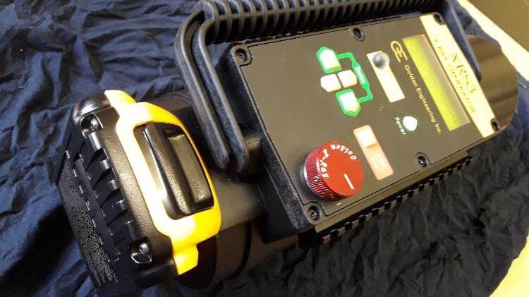
A fémek radiográfiai tompavarratainak vizsgálatánál segítséget jelentettek a korábbi anyagvizsgálati tapasztalataink, illetve a releváns szabványok. A Vidisco impulzus üzemű radiográfiai rendszerének megismerése így gördülékeny volt. Az anyagvizsgálatban ma még nagy arányban analóg készülékeket alkalmaznak, amelyekhez képest a digitális készülékek számos előnnyel bírnak. Idő-, így költséghatékonyságát adja, hogy meglehetősen alacsony sugárzási szintje nem követeli meg az expozíciós terület komplex kialakítását. Az expozíciót követően a felvétel azonnal látható, nem kell előhívó készülék, előhívó szoba, és elmondható, hogy lényegében nincs előhívási idő. Így, ha nem megfelelően sikerült egy felvétel, akkor azt azonnal meg lehet ismételni. Az analóg röntgen készüléknél, ahol nem digitális képalkotó berendezést használnak, legjobb esetben is 10-15 perc, mire egy nem megfelelően sikerült felvételt újra elkészítenek, előhívnak. A digitális rendszernek kevés hátránya van a hagyományos eljáráshoz képest, melyek kis odafigyeléssel kikerülhetők. Például, a készülék nem hálózatról veszi fel a működéséhez szükséges feszültséget, hanem akkumulátorról. A készülék sípoló hangjelzést ad ki, ha merülne az áramellátása, így csak arról kell gondoskodni, hogy legyen feltöltött tartalék akkumulátor. A rendszer másik gyenge pontja a szoftveres vezérlésből adódik. Célszerű a készülék vezérléséhez használt számítógépet csak erre a feladatra dedikálni, hogy az általános, számítógépen végzett munkák ne „használják el” magát a számítógépet, se hardveresen, se szoftveresen. A rendszer további előnyét a kezelő szoftver különböző funkciói adják. A detektálni kívánt anyagfolytonossági hibát méretétől, környezetétől, egyéb ismérveitől függően jobban észlelhetővé lehet így tenni.
A fémek hegesztési varratainak radiográfiai vizsgálatánál a „detection” volt az a szűrő, amellyel a hibák legjobban láthatóvá váltak. Műanyag csöveknél, a finomabb eltérések okán a „revelation” és a „sharpening” funkciókat is alkalmaztuk. Ezek a funkciók a fémeknél nem javítottak jelentősen az észlelhetőségen. A kompozit anyagok és műanyagok vizsgálatával a cél egy ismeretlen, anyagvizsgálat számára releváns szabványokkal nem rendelkező anyagok jobb megismerése volt. Az iparban felhasznált anyagok köre szélesedik, változik, amivel az anyagvizsgálatnak lépést kell tartania. Adott méretű és típusú anyagfolytonossági eltérés más mértékben lehet hiba forrása fém és egy lényegesen alacsonyabb sűrűségű anyag, például a polietilén esetében.

A kompozit anyagok lényege, hogy különböző anyagokból egy kedvező fizikai tulajdonságokkal bíró anyagot alkotnak, és ez esetben, az adott tulajdonságú hibák más jelentőséggel bírhatnak, mint a fémeknél. Éppen ezért hasznos, hogy a Vidisco készülék rendszerével egészen kisméretű anyagfolytonossági eltérések, hiányosságok helyeit és méreteit is meg lehet pontosan határozni.
A fémek radiográfiai vizsgálatára vonatkozó szabványokból kiindulva, számos, fémre jellemző hibatípust kizártunk, és adatokat gyűjtöttünk arról, hogy a műanyagcsövek tükörhegesztéssel való egymáshoz rögzítésénél milyen anyagfolytonossági hiányok milyen gyakorisággal fordulnak elő. Ebből következően elképzelhetőnek tartjuk a műanyagok különböző ipari felhasználásának, jellemző anyagfolytonossági hiányainak olyan irányú kutatását, amely egy releváns szabvány megalkotását célozza meg.
A fémek után a következő vizsgálati feladat a műanyag csövek ultrahangos vizsgálata volt. A kutatás ezen állapotában már volt megfelelő tudásunk a gépek kezeléséről, működéséről. Megismertük a berendezésben rejlő lehetőségeket és alkalmazási módszereket.

Az elkészített felvételek, mérési file-ok értékelésének megismerésével számos lehetőség nyílik a kiértékelés elvégzésére, az eredmények minél szemléletesebb átadására. A műanyagcsövek vizsgálata korlátozásokkal, de megvalósítható. Első és legfontosabb korlát a szabványosítás hiánya. Hagyományos ultrahangos anyagvizsgálatra létezik vizsgálati szabvány (MSZ EN 13100-3), amely a hőre lágyuló félkész termékek hegesztett kötéseinek roncsolásmentes vizsgálatával foglalkozik. Csakhogy a szabványban foglaltak nem adnak információt az értékelésről, csak a vizsgálat elvégzéséréről. És mint azt az előbb írtuk, a szabvány instrukciói hagyományos ultrahangos vizsgálati módszerekre vonatkoznak.

A szabványban foglaltak és a gyakorlati tapasztalatok alapján elmondható, hogy abban az esetben vizsgálhatók a csövek, ha az érintkező felületek között maximum 0,5 mm-es rés van. A vizsgálatokat 160 mm-es, illetve e feletti átmérő esetén tudtuk elvégezni. Következő nehézséget a varrat alakjának, méretének és jellegének megadása jelentette. Fémek esetén a legtöbb varrat alakja és mérete megadható, paraméterezhető a rendszerben, tükörhegesztés esetén viszont a fémekre jellemzőtől eltérő varratalak fog kialakulni, ami mindig az adott feladatnak és daraboknak, alkalmazott technológiai paramétereknek a függvénye. De maga a vizsgálati módszer továbbra is alkalmazható, a vizsgálatot el lehet végezni, a hibák helye meghatározható, maga a hiba méretezhető. Harmadik korlát, vagy nehézség, legyen szó bármilyen műanyag és kompozit termék roncsolásmentes vizsgálatáról, az értékelési szabvány, előírás hiánya. A projekt egyik továbbfejlesztési iránya lehetne egy roncsolásmentes vizsgálatot és értékelést összekapcsoló törésmechanikai kutatás. Ezen kutatás során össze lehetne vetni a roncsolásmentes anyagvizsgálattal kimutatható eltéréseket az eltérések által okozott mechanikai károsodásokkal, törésmechanikai tényezőkkel és tönkremeneteli valószínűségekkel.
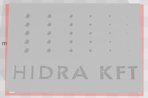
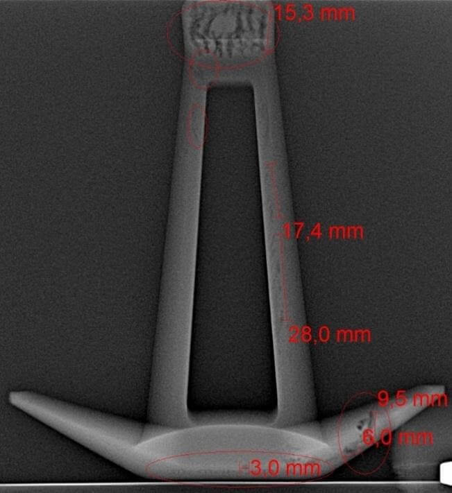
A következő termékek additív gyártási technológiával, 3D nyomtatással készültek. Ezen termékeket első körben radiográfiai eljárás segítségével vizsgáltuk. A fázisvezérelt ultrahangos berendezés alkalmazása számos nehézséggel jár alakos, tört felületű termékek esetén, egyszerűen azért, mert a vizsgálófejet nem lehet a vizsgálati tárgy felszínére helyezni. FDM és SLA technikával készült 3D nyomtatott termékeket vizsgáltunk. Az FDM egy szálhúzásos eljárás, amely során egy műanyag szál megömlesztésével készülnek el a termékek, rétegenként történik a felépítésük. Az SLA jelentése stereolitográfia, az eljárás során egy fényforrás keményíti meg az alapanyagot rétegenként és így készül el a termék. Az alapanyag itt folyékony gyanta, amelyben fény, lézer vagy UV sugárzás hatására keresztkötések alakulnak ki, térhálós szerkezet jön létre. Az elkészült termékek vizsgálata nagyobb kihívást jelentett, mint az eddigi vizsgálati daraboknál, mivel ez anyagvizsgálat szempontjából teljesen új terület. Nincs semmilyen egzakt, általánosan elfogadott módszer vagy iránymutatás se vizsgálatra, sem értékelésre. Kiértékelés során törekedtünk a látottak minél pontosabb, jobb leírására, szem előtt tartva az adott termék gyártására jellemző tulajdonságokat, nehézségeket. A két erősen eltérő gyártási eljárás esetén más-más tapasztalatok születtek. Az FDM eljárással nyomtatott termékek esetén, a gyártás sajátossága, hogy a termékek nem teljesen kitöltöttek, hanem adott alakú és kialakítású kitöltést, „infill-t”, tartalmaz. Ez részben meg tudja nehezíteni, rosszabb esetekben teljesen meggátolja az elkészített radiográfiai felvételek értékelhetőségét. A másik jellegzetesség ebből adódóan, hogy csak egy vékonyabb fal van, ami folyamatos anyagot jelent röntgen sugárzás számára, így nehezebbé válik a határoló felületekben található anyagfolytonossági hiányok megtalálása. Emellett viszont fontos megjegyezni a pozitív tapasztalatokat is. Azáltal, hogy belül kitöltés van a termékeknél, a kitöltés esetleges hibáit és eltéréseit nagyon szépen ki lehet mutatni. A nagyobb méretű és rétegek között tapasztalható rétegelválást is több helyen észleltük. Pontosan meg lehet figyelni és meg lehet határozni a tervezett és valóságos alak közötti eltéréseket. Több alkatrészből álló, de egy nyomtatással gyártott bennszülött termékek csatlakozási pontjai ellenőrizhetők, nem megfelelő gyártás miatt bekövetkező összeolvadásokat meg lehet figyelni.
SLA eljárás esetén kicsit más a helyzet, mivel a gyártási eljárás teljesen más. Itt már jellemzők a teljesen kitöltött, nem üreges belsővel rendelkező termékek. Jobban tudtuk alkalmazni a fém termékek és az irodalomkutatás során megszerzett ismereteket, mert az SLA termékek vizsgálata már jobban hasonlít az öntött acél termékek vizsgálatára. Mint ahogy azt az itt látható felvételeken is észlelni lehet, az esetleges eltéréseket nagy biztonsággal meg lehet találni, fel lehet ismerni és meg lehet állapítani méretüket és elhelyezkedésüket. Az eltéréseket akár a felületen, akár a felület alatt egyező könnyedséggel ki lehet mutatni, vagyis a radiográfiai módszer megfelelően alkalmazható SLA eljárással gyártott, 3D nyomtatott termékek roncsolásmentes vizsgálatára.
A következő termékcsoport, amit vizsgáltunk a réz, vagy egyéb szál gyártásakor használt húzókő. A húzókövek radiográfiai vizsgálata nem vezetett célra. A belső „tölcséres” szakasz más méretűnek látszik a radiográfiai felvételen, mint ami a valós. Ez a feketedés törvényszerűségeiből adódik. A kő anyagában sem találtunk egyik esetben sem anyagfolytonossági hiányt. Viszont a digitális nagyító rendszerrel már meg tudtuk vizsgálni a redukáló kúpot, és a rendeltetésszerű használatból adódó, különböző mértékű kopásokat tapasztaltunk.
A mesterséges hibákat az esetek nagy részében egyszerű szemrevételezéssel is meg lehetett állapítani. Viszont voltak olyan kisméretű mesterséges hibák, melyeknél szükséges volt a nagyítás. A húzókövek gyártása és használata egyaránt nagyfokú precizitás mellett zajlanak. Az esetleges hibák kimutatása egy ugyancsak precíz eszközt igényel, aminek a digitális nagyító berendezés megfelel. Nem tartjuk indokoltnak egy, a húzókövekkel foglalkozó szabvány megalkotását, viszont az eljárási módszer kiváló alapot ad a minőség-ellenőrzéshez és az esetleges hibák okainak feltárásához.
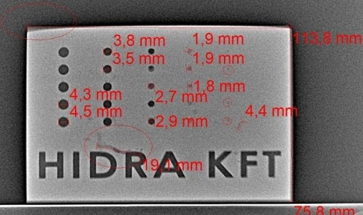
A nyomtatott áramkörök vizsgálata szemrevételezéssel, elektronikai mérőműszerekkel, illetve adott esetben a gyártó saját tesztrendszerével történhet. A digitális nagyító berendezéssel való munkát az áramkörökön levő szennyeződések hátráltathatják, mivel azok eltávolítása a termék roncsolásával járhat. Szélsőséges esetben előfordulhat, hogy nincs lehetőség műszeres, vagy tesztrendszeres vizsgálatra. A radiográfiai vizsgálat megfelelő alternatívának bizonyult. Többrétegű nyomtatott áramkör esetén is egyértelműen kimutathatók a vezetősávok esetleges hibái.


A nagyobb méretű hibák esetében használt „detection” funkció itt már nem adott megfelelő képeket, ilyen kisméretű tárgyaknál a „refining” bírt kiemelt jelentőséggel. Összességében kijelenthető, hogy radiográfiai eljárás tökéletesen alkalmas a nyomtatott áramkörök vizsgálatára, így a műanyagokhoz hasonlóan elképzelhetőnek tartunk egy olyan kutatást a jövőben, melynek eredménye a kompozit anyagok, illetve a kompozit anyagokból készült termékek minőségét szabályozza, akár szabványok formájában, különböző anyagvizsgálati módszerek esetén.
A termékeket radiográfiai vizsgálata után a fázisvezérelt ultrahangos vizsgálat következett. Ha ultrahangos roncsolásmentes anyagvizsgálatot szeretnénk végezni, akkor szükséges a vizsgálati etalon.

Az ismert mérettel és formával rendelkező etalon segítségével lehet például a vizsgálati tartományt bekalibrálni, az érzékenységet meghatározni és ellenőrizni. Jelen termékek esetén is a fémeknél szabványosított ismereteket vettük kiindulási alapnak és az itt megszerzett tudást próbáltuk átültetni az FDM eljárással gyártott termékek vizsgálatára. A vizsgálati file elkészítése után lehet elkezdeni kalibrálni a berendezést. Az első lépés kalibráció során mindig a 0 pont és a mérési tartomány hitelesítése, azaz a geometriai hitelesítés elvégzése. Nem sikerült visszhangjeleket előállítani a vizsgálati etalonok segítségével, ebből adódóan sajnos nincs semmi, amit ábrával lehetne szemléltetni. Hiába próbálkoztunk több módszer mellett egyéb praktikákkal. Ennek oka lehet egyrészt maga a technológia. Az egyes rétegek nem egyszerre szilárdulnak meg, így nem alakul ki teljesen homogén anyagszerkezet, az egyes szálak közé mikroszkopikusan kicsi levegő vagy egyéb anyagok kerülhetnek, amik ellenállásként viselkednek az ultrahang terjedésével szemben. A kitöltés javítására technológiai paraméterek változtatását lehet esetleg eszközölni, de külön kellene vizsgálni az egyes paraméterek hatását a kitöltésre, az egyes szálak és rétegek közötti homogén kapcsolatára.
A lencsék vizsgálata során a legfontosabb tapasztalatot a mikroszkópos és radiográfiai felvételek közötti különbségek jelentették. A különbség az adott hiba keletkezéseinek körülményeiből adódik. A csorbulások és karcolások esetében tapasztalhattuk, hogy az adott pontból hiányzó anyag a hiba mentén is felgyűrődhet, ami a radiográfiai felvételen egyfajta anyagtöbbletnek hat. A vizsgálat előnyét az adta meg, hogy szabad szemmel is „beleláttunk” az anyagba, a digitális nagyítóval az esetleges eltéréseket rögzíteni és ebből adódóan méretezni is lehet. A röntgenfelvételek másként „érzékelték” az eltéréseket.
A radiográfiai és mikroszkópos felvételek közötti különbség továbbá adódik abból is, hogy az anyag felülete és a hiba kezdőpontja között milyen szögű a szintkülönbség. Magyarán, minél meredekebb az eltérés „fala”, annál pontosabban lehet meghatározni a hiba kiterjedését radiográfiai úton, mivel ez a meredekség meghatározza a kontúrt.

Az utolsó termékkategóriánk a különböző alapanyagokból felépülő saválló gömbcsapok. Két különböző alapanyagból – fém vagy műanyag – előállított szerkezetben találhatók eltérő anyagminőségű, de azonos funkciót szolgáló alkatrészek.
A saválló acélból készült gömbcsapok hegesztési varratainak radiográfiai vizsgálata során jobb felvételeket sikerült készítenünk, mint azt reméltük az anyag vastagsága, és a termék felületének komplexitása alapján. A gömbcsap „csővezeték” szakasza vastag falú, kis átmérőjű, rövid, a környezetében számos különböző méretű és kiterjedésű felületi rész van (gömbcsap szerkezete, karima stb.). A gömbcsap minden attribútuma miatt úgy gondoltuk, hogy többek között falkiegyenlítő hatása miatt izotóppal lehetne a legjobb felvételeket készíteni. A Vidisco készülék vezérlő szoftverében az úgynevezett „average”, vagyis átlagoló funkciónak köszönhetően lehetőség nyílik olyan vastagságok átvilágítására, melyeket alapvetően izotóppal végeznénk el. A gömbcsap belső szerkezetének radiográfiai vizsgálata viszont nem hozott megfelelő eredményeket, mivel annak komplexitását már nem tudtuk áthidalni rendelkezésre álló eszközeinkkel. A gömb felületén levő hibák legfeljebb igen extrém hibaméret esetében mutathatók ki. Azok a gömbszerkezeten levő mesterséges hibák, melyek az általunk vizsgált termékeken vannak, nincsenek olyan méretűek, hogy azt radiográfiai úton ki lehessen mutatni.

A műanyag házban helyet foglaló gömbcsapok esetén a radiográfiai felvételek alapján elmondható, hogy a termékeken található mesterséges és természetese hibákat, folytonossági hiányokat a legtöbb esetben ki tudtuk mutatni. Abban az esetben, amikor nem sikerült a mesterséges indikáció kimutatása, a folytonossági hiány méretében rejlett a probléma, nem pedig a vizsgálati rendszerben, vagy a hiba pozíciójában (hasonló jellegű de mélyebb repedést például minden probléma nélkül ki tudtunk mutatni).
Az eljárás előnye mindkettő alapanyagú golyóscsap esetén a könnyű vizsgálhatóság. Az egyes alkotó alkatrészeket adott esetben egyesével, szétszerelt állapotban kellene vizsgálni. A radiográfiai rendszer modernségének, alkalmazott technológiájának és hordozhatóságának köszönhetően, a termékeket akár beépített állapotban is lehet ellenőrizni. Vagyis, szétszerelés nélkül is megfelelő információt kaphatunk az elemek állapotáról.
A mobil vizsgálókocsi

Az elvégzett kutatási-fejlesztési pályázat során tehát elmondható, hogy sikerült egy olyan anyagvizsgálatokra és anyagvizsgálati oktatásra alkalmas mobil vizsgálókocsit megalkotni, ami egyezik a célkitűzésekben megfogalmazott igényekkel, elvekkel és módszerekkel. A platform tökéletesen alkalmas fém, műanyag és kompozit alapanyagú termékek roncsolásmentes vizsgálati feladatainak elvégzésére. Mobilitásának köszönhetően, nehezebb környezeti körülmények között található vizsgálati helyszínre is el lehet jutni vele. A választott berendezések és módszerek alkalmazásával teljeskörű, felületi és térfogati anyagvizsgálati feladatok oldhatók meg, tehát 100 %-os ellenőrzése biztosított a vizsgált termékeknek, alkatrészeknek. Olyan innovatív termékek vizsgálatához sikerült vizsgálati módszert kifejleszteni, amilyenekkel eddig hallgatóink nem találkozhattak az anyagvizsgálat során. Gondolunk itt például a nyomtatott áramköri lapokra, vagy additív gyártással előállított termékekre. A vizsgálati módszerek könnyen tanulhatók, és taníthatók.

A platform tökéletesen alkalmazható oktatási célokra is. Az utánfutó kialakításának köszönhetően kifejezetten alkalmas kihelyezett tanfolyamok, bemutatók megtartására, mivel az egyik oldalsó felület teljes mértékben felnyitható. A választott berendezések is nagy mértékben hozzájárulnak a minél innovatívabb, jövőbe mutató műszaki ismeretek hatékony átadásához. A berendezések egy része számítógép által vezérelt. Másik része olyan önálló rendszert alkot, ami számítógéphez, monitorhoz, kivetítő vászonhoz csatlakoztatható. Mindkét esetben, az elvégzett feladatokra, beállításokra és folyamatokra vonatkozó információk nagyon egyszerűen megoszthatók több emberrel is. A radiográfiai rendszer biztonsági követelményei is a hatékony oktatást szolgálják, mivel az ismert anyagvizsgáló röntgencsövek közül az általunk választottaknak vannak a legkevésbé szigorú sugárzásvédelmi követelményei. Összességében elmondható, hogy a mobil roncsolásmentes anyagvizsgálati platformot az előzetes terveknek megfelelően sikerült megvalósítani.
